
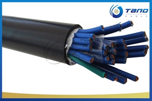


APPLICATION of PE-OS-PVC Instrumentation Cable
The unarmored versions (Part 1 Type 1) PE-OS-PVC Instrumentation Cable are generally use for indoor installation and suitable for wet and damp areas. Generally used within industrial process manufacturing plants for communication, data and voice transmission signals and services, Also used for the interconnection of electrical equipment and instruments, typically in petroleum industry.
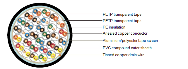
CONSTRUCTION of PE-OS-PVC Instrumentation Cable
MECHANICAL AND ELECTRICAL PROPERTIES of PE-OS-PVC Instrumentation Cable
Operating temperature: -40˚C up to + 70˚C (fixed installation)
0˚C to +50˚C (during operation)
Minimum bending radius: 5 x OD
|
Conductor Area Size |
mm 2 |
0.5 |
0.5 |
0.75 |
1 |
1.5 |
||
|
Conductor Stranding |
No. x mm |
1 x 0.8 |
16 x 0.2 |
24 x 0.2 |
1 x 1.13 |
7 x 0.53 |
||
|
Conductor Resistance Max |
ohm/km |
36.8 |
39.7 |
26.5 |
18.2 |
12.3 |
||
|
Insulation Resistance Min |
Gohm/km |
5 |
5 |
5 |
5 |
5 |
||
|
Capacitance Unbalance At 1 kHz(pair to pair screen) |
pF/250m |
250 |
||||||
|
Max. Mutual Capacitance @ 1 kHz for Non OS or OS cables (except one-pair and two- pairs) |
pF/m |
115 |
115 |
115 |
115 |
120 |
||
|
Max. Mutual Capacitance @ 1 kHz IS/OS cables (include 1 pair and 2 pair) |
pF/m |
75 |
75 |
75 |
75 |
85 |
||
|
Max. L/R Ratio for Adjacent Cores(Inductance/ Resistance) |
μH/ohm |
25 |
25 |
25 |
25 |
40 |
||
|
|
Core to Core |
V |
1000 |
1000 |
1000 |
1000 |
1000 |
|
|
Test Voltage |
Core to Screen |
V |
1000 |
1000 |
1000 |
1000 |
1000 |
|
|
Rated voltage Max |
V |
300/500 |
300/500 |
300/500 |
300/500 |
300/500 |
||
PARAMETER of PE-OS-PVC Instrumentation Cable
|
No. of Pairs |
No. and Dia. of Wires |
Nominal Conductor Cross- Sectional Area |
Nominal Thickness of Insulation |
Nominal Thickness of Sheath |
Nominal Dia. of Cable |
Approx. Weight |
|
|
No./mm |
mm2 |
mm |
mm |
mm |
kg/km |
|
1 |
1/0.8 |
0.5 |
0.5 |
0.8 |
5.5 |
35 |
|
2 |
1/0.8 |
0.5 |
0.5 |
0.8 |
6.8 |
55 |
|
5 |
1/0.8 |
0.5 |
0.5 |
1.1 |
10.9 |
125 |
|
10 |
1/0.8 |
0.5 |
0.5 |
1.2 |
14.4 |
215 |
|
15 |
1/0.8 |
0.5 |
0.5 |
1.2 |
16.5 |
300 |
|
20 |
1/0.8 |
0.5 |
0.5 |
1.3 |
18.8 |
385 |
|
30 |
1/0.8 |
0.5 |
0.5 |
1.3 |
22.3 |
545 |
|
50 |
1/0.8 |
0.5 |
0.5 |
1.5 |
28.5 |
875 |
|
1 |
16/0.2 |
0.5 |
0.6 |
0.8 |
6.2 |
60 |
|
2 |
16/0.2 |
0.5 |
0.6 |
0.8 |
7.6 |
80 |
|
5 |
16/0.2 |
0.5 |
0.6 |
1.1 |
12.4 |
210 |
|
10 |
16/0.2 |
0.5 |
0.6 |
1.2 |
16.5 |
340 |
|
15 |
16/0.2 |
0.5 |
0.6 |
1.3 |
19.2 |
440 |
|
20 |
16/0.2 |
0.5 |
0.6 |
1.3 |
21.7 |
570 |
|
30 |
16/0.2 |
0.5 |
0.6 |
1.5 |
26.4 |
780 |
|
50 |
16/0.2 |
0.5 |
0.6 |
1.7 |
33.4 |
1130 |
|
1 |
24/0.2 |
0.75 |
0.6 |
0.8 |
6.7 |
75 |
|
2 |
24/0.2 |
0.75 |
0.6 |
0.9 |
8.4 |
100 |
|
5 |
24/0.2 |
0.75 |
0.6 |
1.2 |
13.8 |
250 |
|
10 |
24/0.2 |
0.75 |
0.6 |
1.3 |
18.4 |
450 |
|
15 |
24/0.2 |
0.75 |
0.6 |
1.5 |
21.1 |
600 |
|
20 |
24/0.2 |
0.75 |
0.6 |
1.5 |
24.4 |
920 |
|
30 |
24/0.2 |
0.75 |
0.6 |
1.7 |
29.5 |
980 |
|
50 |
24/0.2 |
0.75 |
0.6 |
2 |
37.6 |
1690 |
|
1 |
1/1.13 |
1 |
0.6 |
0.8 |
6.6 |
85 |
|
2 |
1/1.13 |
1 |
0.6 |
0.8 |
8 |
115 |
|
5 |
1/1.13 |
1 |
0.6 |
1.2 |
13.5 |
290 |
|
10 |
1/1.13 |
1 |
0.6 |
1.2 |
17.7 |
500 |
|
15 |
1/1.13 |
1 |
0.6 |
1.3 |
20.6 |
670 |
|
20 |
1/1.13 |
1 |
0.6 |
1.5 |
23.8 |
950 |
|
30 |
1/1.13 |
1 |
0.6 |
1.5 |
28.4 |
1030 |
|
50 |
1/1.13 |
1 |
0.6 |
2 |
36.6 |
1750 |
|
1 |
7/0.53 |
1.5 |
0.6 |
0.8 |
7.5 |
100 |
|
2 |
7/0.53 |
1.5 |
0.6 |
0.9 |
9.3 |
150 |
|
5 |
7/0.53 |
1.5 |
0.6 |
1.2 |
15.6 |
360 |
|
10 |
7/0.53 |
1.5 |
0.6 |
1.3 |
20.9 |
690 |
|
15 |
7/0.53 |
1.5 |
0.6 |
1.5 |
24.6 |
880 |
|
20 |
7/0.53 |
1.5 |
0.6 |
1.5 |
27.8 |
1230 |
|
30 |
7/0.53 |
1.5 |
0.6 |
1.7 |
33.7 |
1560 |
|
50 |
7/0.53 |
1.5 |
0.6 |
2 |
43 |
2400 |
